| EPIDINO
(Updated
2019-01-05) 日 本語 Die Idee, ein Epi-Alarmgeraet mit dem Arduino zu bauen kam, als der Sensor des Epi-Care Geraetes nicht mehr arbeitete und eine schnelle Loesung gefunden werden musste. The idea of building an Epi-Alarm device with the Arduino came when the sensor of the Epi-Care device stopped working and a quick solution had to be found. Und so entstand das Epidino. Ein Warngeraet fuer tonisch-klonische epileptische Anfälle mit Uebertragung des Alarms ins Mobilfunknetz. And that's how Epidino came to be. An alarm device for tonic-clonic epileptic seizures with transmission of the alarm to the mobile phone network. Die erste Version entstand mit einem ARDUINO UNO, einem Shield fuer die Bauteile und einem GSM-Shield. The first version was created with an ARDUINO UNO, a shield for the components and a GSM shield. Danach wurde ein neues auf einer Platine entworfen, mit dem sich verschiedene Loesungsmoeglichkeiten verwirklichen lassen konnten. After that, a new one was designed on one board, with which different solution possibilities could be realized. Hier wird die neueste Version gezeigt. Als Sensoren werden nur Piezoelemente verwendet, die sich in der Praxis am besten bewaehrt haben. Da sie auf Druckunterschiede, und nicht auf Bewegung, reagieren, arbeiten sie bei jedem Bett, auch bei fester Unterlage zuverlaessig. Here is the latest version shown. As sensors only piezo elements are used, which have proven in practice best. Because they respond to differences in pressure, not movement, they work reliably with every bed, even on a firm surface. Es kann ein GSM shield zum Senden einer SMS aufgesteckt werden. A GSM shield can be attached to send a SMS. Hat man kein GSM shield zur Verfuegung, so kann auch ein anderes Telefon-Wahlgeraet angeschlossen werden. Oder auch einfach nur ein Buzzer ueber eine Leitung ins Zimmer nebenan. If you do not have a GSM shield available, you can also connect another telephone dialer. Or just a buzzer over a line into the room next door. Mit den drei Potentiometern ist eine gute Einstellung der Sensor-Empfindlichkeit, der Dauer ("Wartephase") und der Alarmschwelle moeglich. With the three potentiometers a good adjustment of the sensor sensitivity, the duration ("waiting phase") and the alarm threshold is possible. Mit einem vierten Potentiometer koennen vier verschiedene Telefonnummern (die im Programm angegeben sind) gewaehlt werden. With a fourth potentiometer four different phone numbers (indicated in the program) can be selected. So sieht das Epidino jetzt aus. Der Koffer (der Firma "rosecase") ist kleiner als der der letzten Version. Außenmaße (BxHxT): ca. 275x231x65 mm That's what the Epidino looks like now. The suitcase (the "rosecase" company) is smaller than the last version. External dimensions (WxHxD): approx. 275x231x65 mm
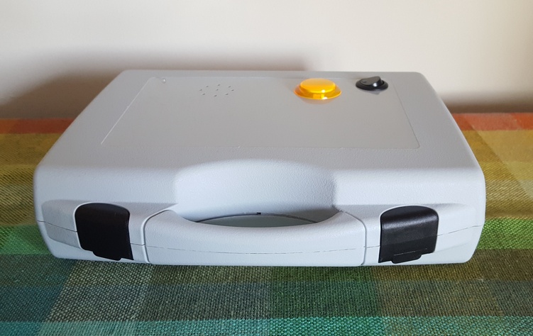 Rechts der Ein-/Ausschalter, links daneben die beleuchtete orangefarbene Stopptaste, ganz links, kaum zu erkennen, die zweifarbene LED. To the right there is of the on / off switch, to the left next to it the illuminated orange stop-button, on the far left, hardly recognizable, the two-colored LED. Sobald eine Bewegung festgestellt wird, startet der Timer, und die rote LED leuchtet kurz auf. Danach leuchtet die gruene bis zum Ende der eingestellten Wartephase (Dauer). Once a movement is detected, the timer starts and the red LED lights up briefly. After that, the green light will be on until the end of the set waiting period (duration). - Wird innerhalb der Wartephase erneut eine Bewegung festgestellt, so wird der Timer auf Null zurueckgesetzt. - Erreicht der Timer das Ende der Wartephase, ohne dass eine Bewegung festgestellt wurde, so erlischt die gruene LED. - If a movement is detected again during the waiting phase, the timer is reset to zero. - If the timer reaches the end of the waiting phase without a movement being detected, the green LED goes out. Bei jeder Bewegung innerhalb der Wartephase (Dauer) verlaengert sich sozusagen die Ueberwachungszeit. With each movement within the waiting phase (duration), so to speak, the monitoring time lengthens. Wurde die Alarmschwelle durch sukzessives Verlaengern des Timers durch aufeinanderfolgende Bewegungen ueberschritten, so wird der Alarm ausgeloest. If the alarm threshold has been exceeded by successively extending the timer by successive movements, the alarm is triggered. Die Wartephase wird durch die gruene LED angezeigt. The waiting phase is indicated by the green LED. Bewegungen werden durch die rote LED signalisiert. Movements are signaled by the red LED. :: Zweifarbige LED :: Two-color LED  :: Anschluesse an der Rueckseite :: Connections at the back  An der Rueckseite des Koffers befinden sich die Anschluesse. Momentan wird nur ein Sensor angeschlossen an [Sens 1]. Statt eines zweiten Sensors wird ein Stecker eingesteckt, der den analogen Eingang auf LOW (0 V) setzt. Ganz rechts der 12V-Netzadapter-Anschluss. At the back of the case are the connections. Currently only one sensor is connected to [Sens 1]. Instead of a second sensor, a plug is inserted, which sets the analog input to LOW (0 V). On the far right, the 12V power adapter connector. Die verschiendenen Verwendungsmoeglichkeiten der Ein- und Ausgaenge werden hier gezeigt: Anschlussbeispiele (.pdf) The different ways of using the inputs and outputs are displayed here: Connection examples (.pdf) Bei Alarm wird eine SMS geschickt, in der auch mitgeteilt wird, ob der Sensor, das an [Alrm IN] angeschlossene Geraet oder die SOS-Taste (falls angeschlossen) den Alarm ausgeloest hat. When an alarm is sent, an SMS will be sent informing you whether the sensor, the device connected to [Alrm IN] or the SOS button (if connected) has triggered the alarm. :: Der Piezo-Sensor :: Piezo sensor Hier wird ein einfacher Sensor gezeigt A simple sensor is shown here 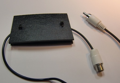 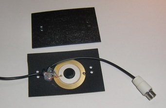 An den Piezo-Sensor koennen weitere Piezo-Sensoren angeschlossen werden. Additional piezo sensors can be connected to the piezo sensor. 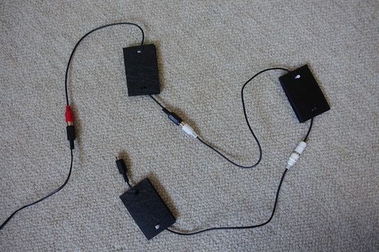 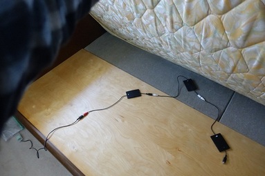 >>> Sensorstreifen eignen sich bessser, siehe hier (pdf) >>> Sensor strips are more practical, see here (pdf) Der Piezo-Sensor wird ueber eine Box mit RC-Glied angeschlossen. The piezo sensor is connected via a box with RC element. Piezo Sensor -->  -->
[Sens 1] connector -->
[Sens 1] connector :: Tuerlampe :: Door Lamp Zwei LEDs sind ueber der Tuer angebracht und ueber ein Kabel an [DOOR Lamp] des Epidino angeschlossen. Bei eingeschaltetem Epidino leuchten sie und signalisieren dem Nachtdienst, dass das Geraet in Betrieb ist. Two LEDs are mounted over the door and connected to [DOOR Lamp] of the Epidino. When the Epidino is switched on, they light up and signal the night service that the device is in operation. 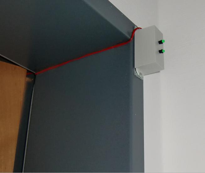 :: Stopptaste :: Stop button Diese Stopptaste besitzt dieselbe Funktion wie die am Geraet selbst. This stop button has the same function as the one on the device itself. 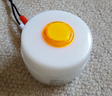 Stopptaste an [STOP button] und fuer die Beleuchtung an [12 V] (roter Stecker) angeschlossen Connected to [STOP button] and to [12 V] (red connector) for the lighting Wird ein Alarm ausgeloest, so verbleibt bis zum Senden der Alarm-SMS eine kurze Zeit, in der der Alarm mit der Stopptaste storniert werden kann, so dass die Betreuungsperson keine Alarm-SMS erhaelt. If an alarm is triggered, there remains a short time until the alarm SMS is sent, in which the alarm can be canceled with the stop button, so that the caregiver does not receive an alarm SMS. Ist die SMS geschickt, so ertoenen kurze Pieptoene ("po! po! po! ...") solange, bis die Stopptaste gedrueckt wird. Bei Druecken der Stopptaste wird das Epidino zurueckgesetzt, und eine SMS mit der Nachricht "Alarm wurde gestoppt" wird gesendet. If the SMS is sent, then short beeps ("po po po ...") continue until the stop button is pressed. Pressing the Stop key will reset the Epidino and send an SMS with the message "Alarm Stopped". :: SOS-Knopf :: SOS button Kann an [SOS button] angeschlossen werden. Auch Mitbewohner koennen durch einfaches Druecken der Taste Hilfe rufen. Connected to [SOS button] . Roommates can call for help by simply pressing the button. :: Epidino mit SOS-Empfaenger und SOS-Taste :: Epidino with SOS receiver and SOS button >>>> Einzelheiten siehe: Drahtlose SOS-Taste >>>> For details see: Wireless SOS button 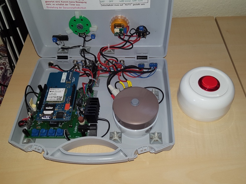 :: Handy :: Mobile phone  Als "Klingel" wird ein Prepaid
Handy verwendet. Das Mitteilungssignal
ist auf "Rufton" "Destiny" (oder anderes Klangmuster) eingestellt, so
dass bei Empfang der SMS ein laengeres Signal ertoent. (Bei "Standard"
oder "Einzelton" kommt es vor, dass das kurze Signal ueberhoert wird.) Als "Klingel" wird ein Prepaid
Handy verwendet. Das Mitteilungssignal
ist auf "Rufton" "Destiny" (oder anderes Klangmuster) eingestellt, so
dass bei Empfang der SMS ein laengeres Signal ertoent. (Bei "Standard"
oder "Einzelton" kommt es vor, dass das kurze Signal ueberhoert wird.)As a "bell" a prepaid mobile phone is used. The message signal is set to "Ringer" "Destiny" (or other sound pattern), so that a longer signal sounds on receipt of the SMS. (In "Standard" or "Single Tone", it happens that the short signal is not heard.) :: Wenn kein GSM shield verwendet wird :: If no GSM shield is used Alarm-Summer an [ Alarm Out Relay] [12V] anschliessen. Dieser kann ueber eine lange Leitung in ein anderes Zimmer verlegt werden. Connect an alarm buzzer to [Alarm Out Relay] [12V] which is placed in another room. 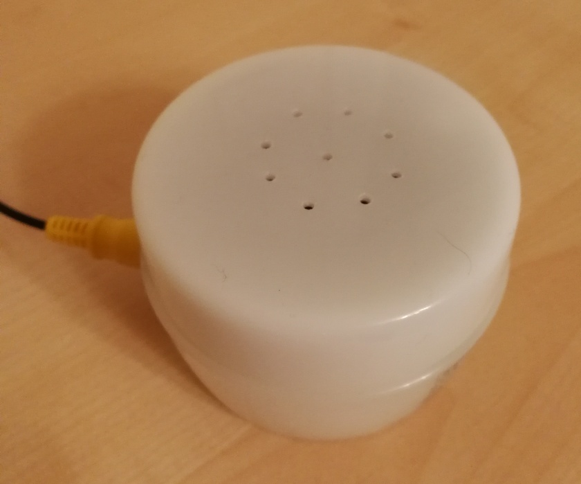 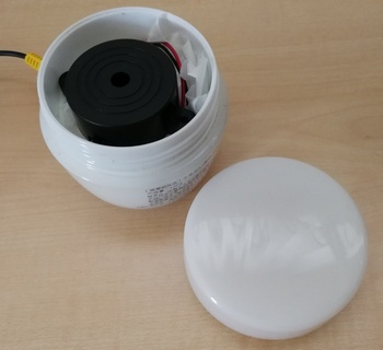 :::::::::::::::::::::::::::::::::::::::::::::::::::::::::::::::::::::::::::::::::::::: :::::::::::::::::::: Und nun zu den technischen Details :::::::::::::::::: :::::::::::::::::::: And now to the technical details :::::::::::::::::::::: :: Ohne GSM shield. :: Without GSM shield. 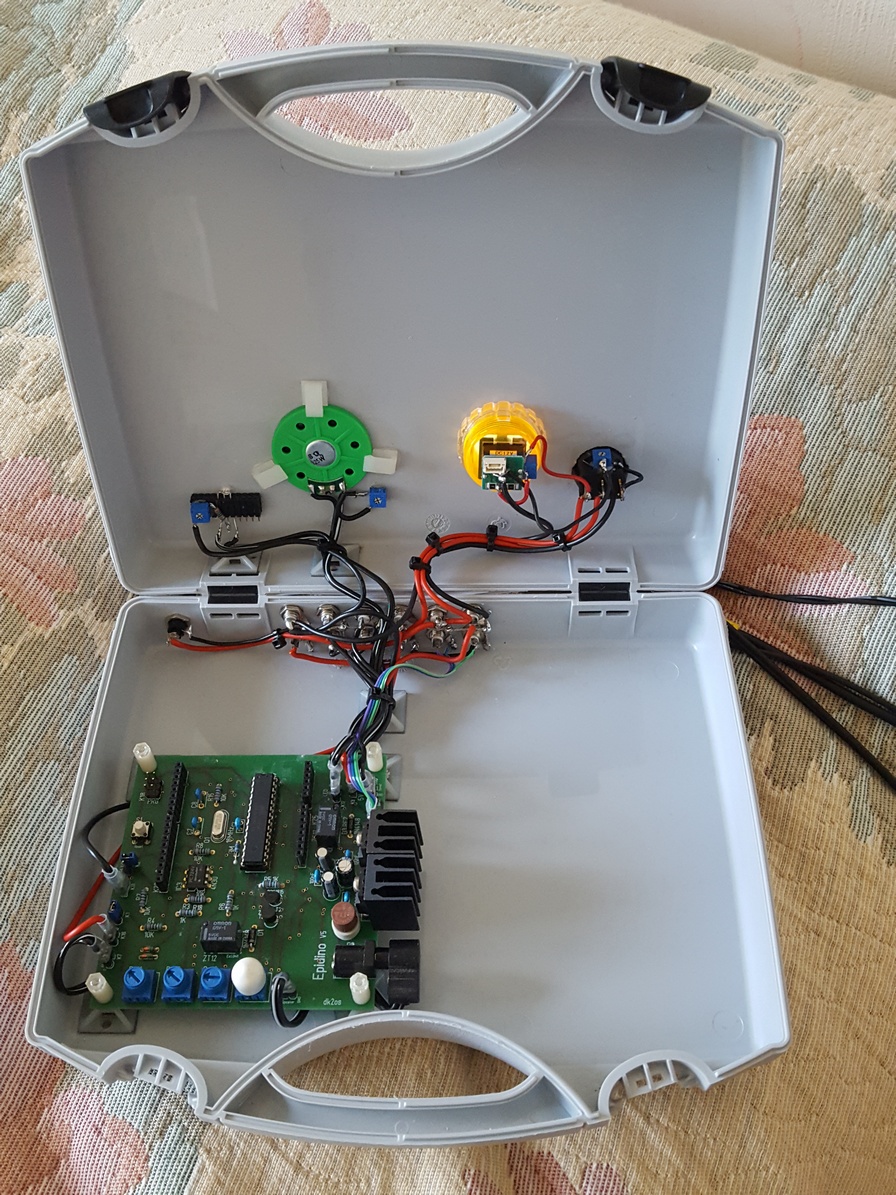 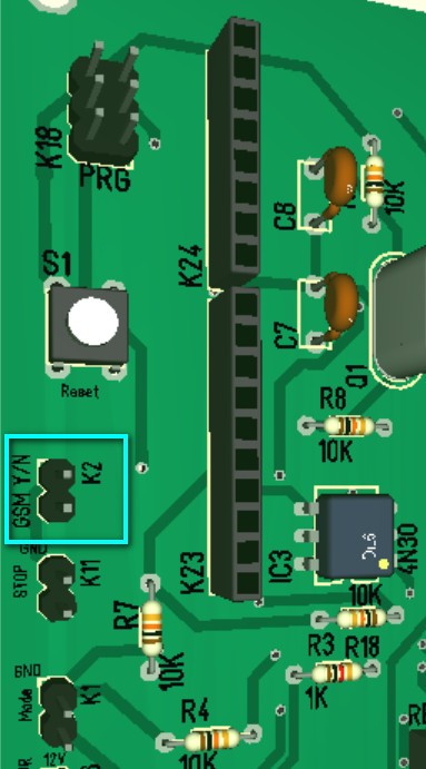 Wenn ein GSM shield verwendet wird, dann muss hier ein Jumper gesetzt werden. If a GSM shield is used, then a jumper must be set here. :: Mit aufgestecktem GSM shield. :: With attached GSM shield. 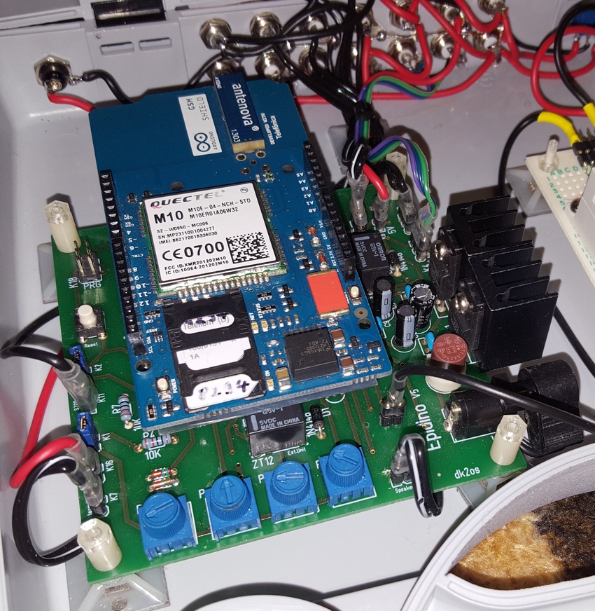 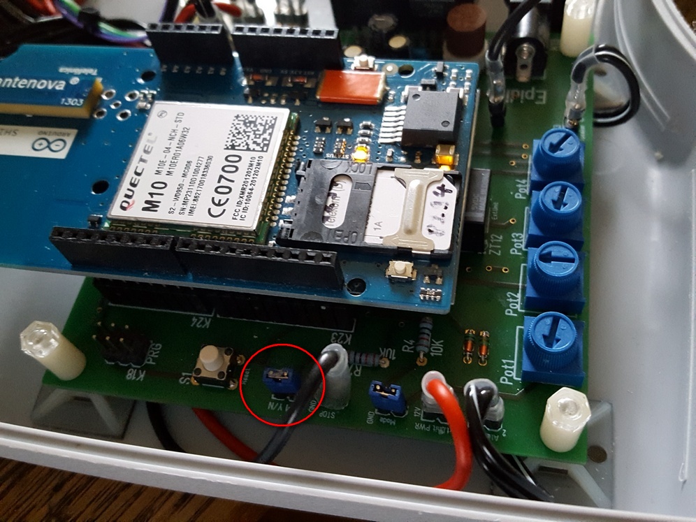 Hier ist der Jumper fuer das GSM shield zu sehen (roter Kreis). Jumper gesetzt: GSM shield wird verwendet. Kein Jumper: Kein GSM shield vorhanden oder es wird nicht verwendet. Here you can see the jumper for the GSM shield (red circle). Jumper set: GSM shield is used. No jumper: No GSM shield exists or it is not used. :: Die Stopptaste ist mit einer LED ausgestattet. :: Stop button with LED 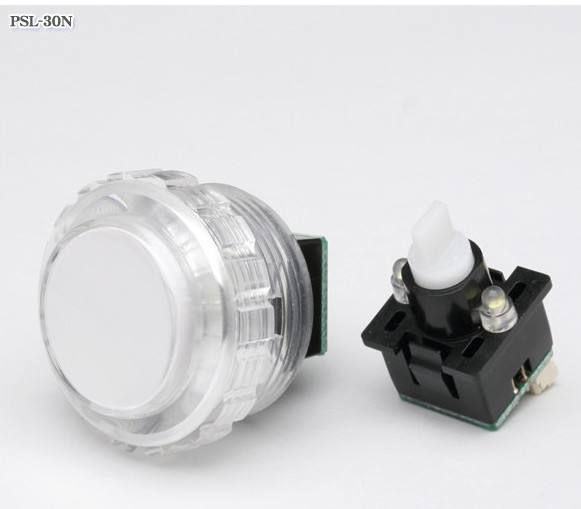 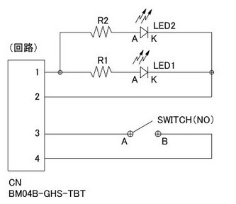 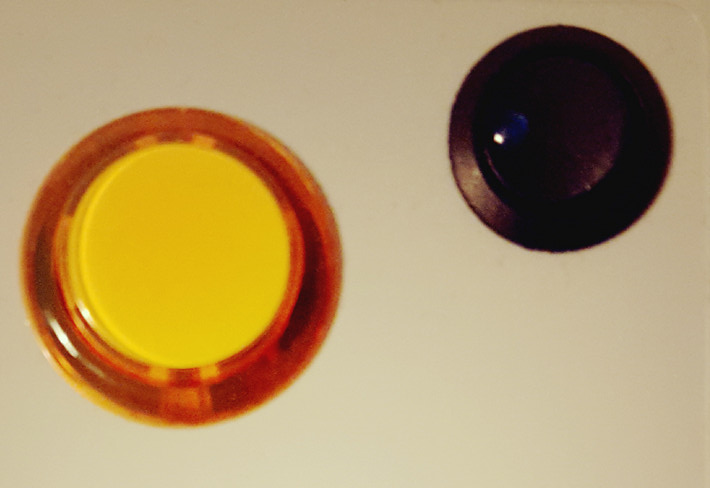 Epidino
ausgeschaltet Epidino
ausgeschaltet OFF 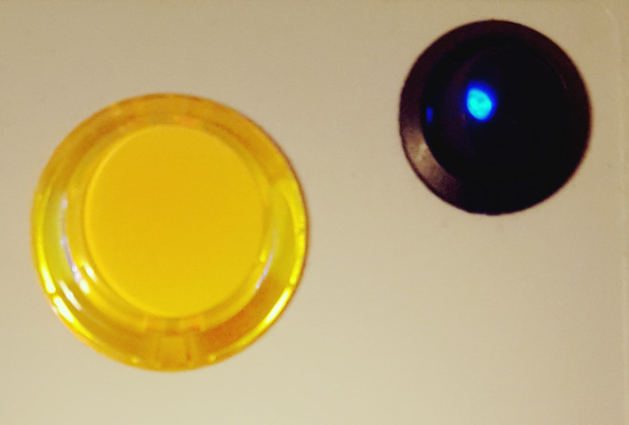 Epidino eingeschaltet Epidino eingeschaltetON Hat man keine Stopptaste mit eingebauter LED zur Verfuegung, kann man diese mit einer unten angeklebten LED beleuchten, damit sie im Dunkeln besser zu erkennen ist. If you do not have a stop button with built-in LED, you can illuminate it with a LED as seen in the picture. 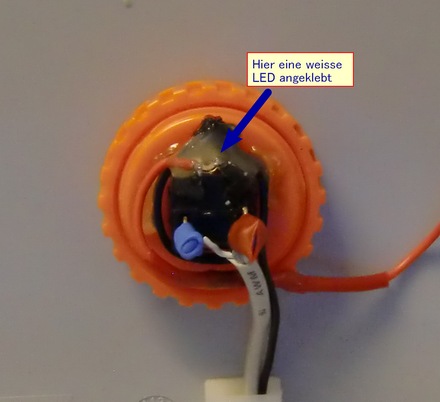 :: Schaltplan und Platine, erstellt mit TARGET 3001! :: Circuit and PCB designed with TARGET 3001! 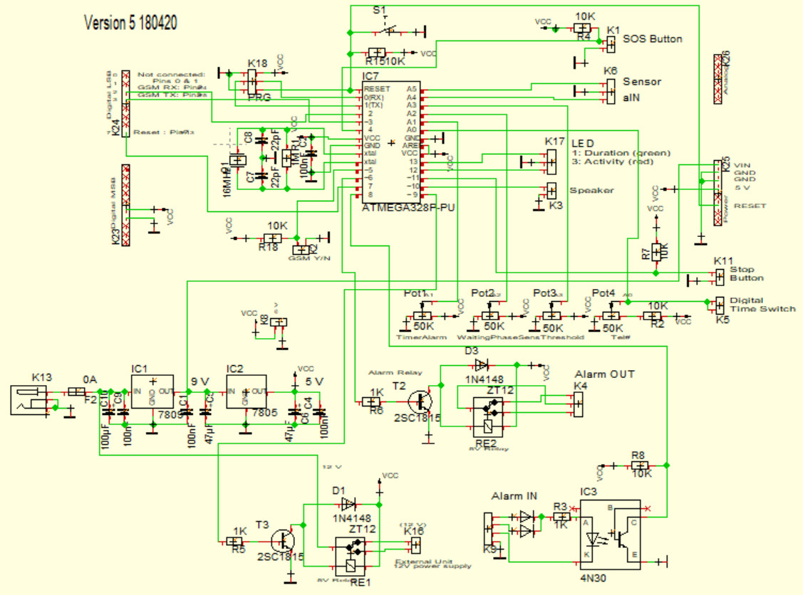 >>>> Schaltplan herunterladen(.pdf) >>>> Download circuit diagram (.pdf) :: Die Platine :: PCB 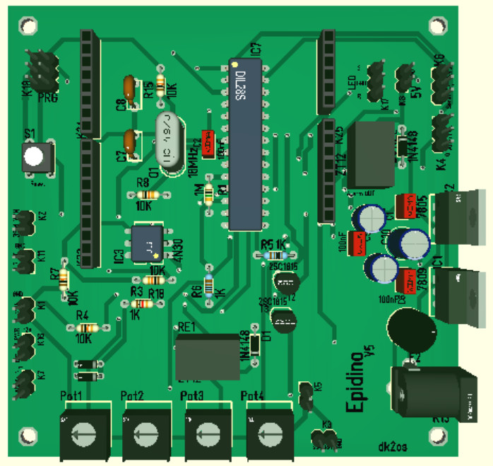 >>>> Erklaerung der Potentiometer zur Einstellung (pdf) >>>> Explanation of the potentiometer for adjustment (pdf) :: Teileliste fuer Platine :: Parts list for PCB
:: Die Buchsen an der Rueckseite :: RCA sockets at the rear 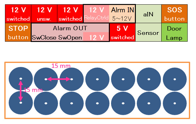 >>>> Schablone fuer die Buchsen herunterladen(.pdf) >>>> Download template for rear (.pdf) 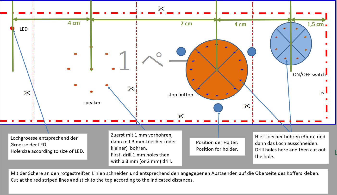 >>>> Schablone fuer die Oberseite herunterladen (.pdf) >>>> Download template for top (.pdf) >>>> Siehe hier, wie die Teile angebracht werden. >>>> See here how the parts are attached. :: LED, Lautsprecher, Stopp-Taste, Ein-/Ausschalter :: LED, loudspeaker, stop button, on / off switch 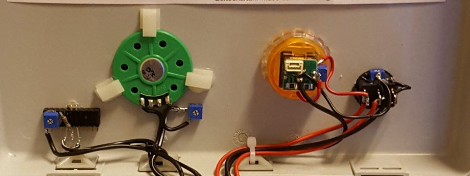 Die Helligkeit der LEDs kann mit den kleinen Trimmpotis (blau) eingestellt werden. Auch die Lautstaerke kann eingestellt werden. For each LED there is a variable resistor (blue) for changing the brightness. And the volume of the speaker can be changed by one. 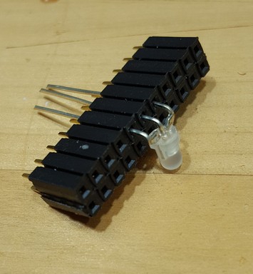 Anbringung der LED. Mit doppelseitigem Klebeband an der Innenseite des Deckels befestigen. How to fix the LED. Attach this with double-sided adhessive tape to the case. :: Anschlussplan, erstellt mit TARGET 3001! :: Connection diagram (designed with TARGET 3001!) 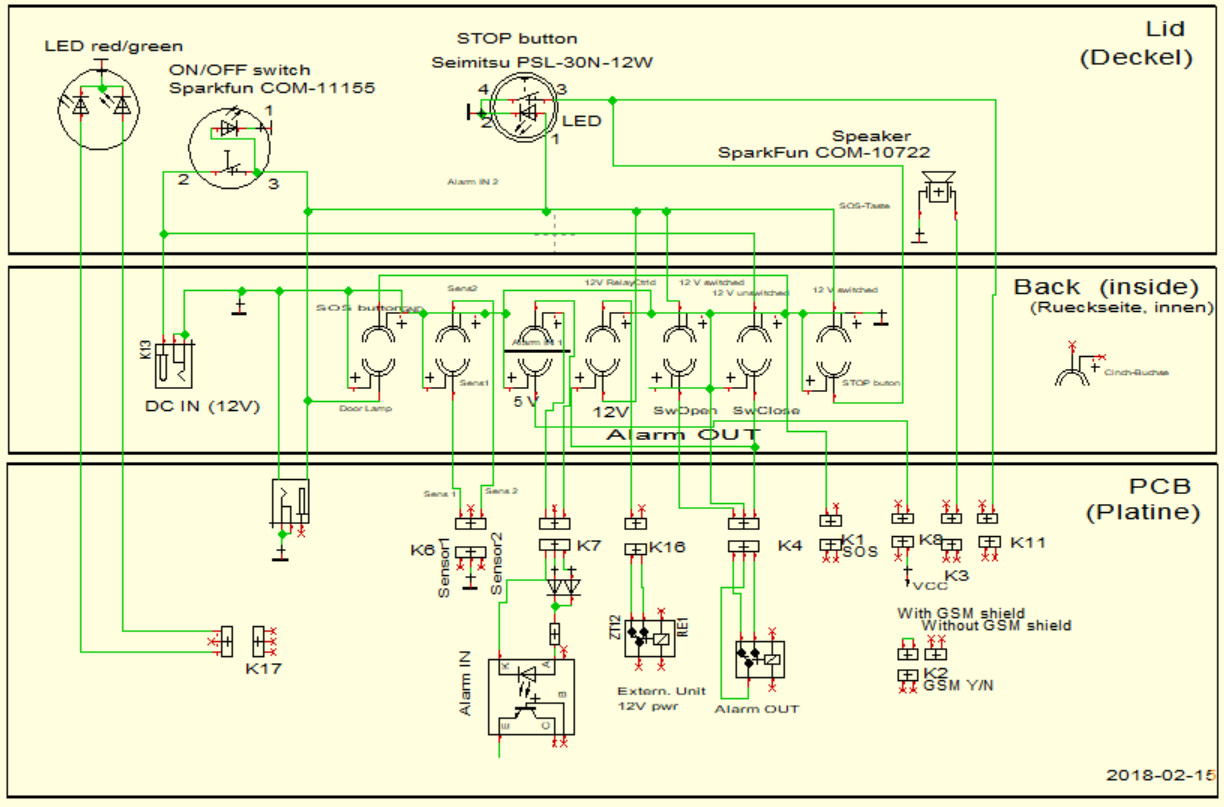 Die Beschaltung ist von der Kofferinnenseite her gezeigt. The connecting diagram is shown from the inside of the case. >>>> Buchsen-Anschlussplan herunterladen(.pdf) >>>> Download socket diagram (.pdf) >>>> Erklaerung der Anschluesse herunterladen(.pdf) >>>> Download sockets explanation (.pdf) :: Box zum Anschluss des Piezo-Sensors :: Box for connecting the piezo sensor -- Das RC-Glied (Kondensator/Widerstand) ist in einem Plastikkaestchen in der Zuleitung des Piezo-Sensors untergebracht. -- R/C box for piezo sensor (left: cable with RCA plug for connection to the unit, right: connection for piezo sensor) 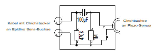  Bipolarer (NP) Elektrolytkondensator Bipolarer (NP) Elektrolytkondensator non-polar (NP) electrolytic Condensor 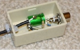 :: Anschluss eines anderen Warngeraetes (z.B. Epi-Care free mit Armband-Sensor) :: Connecting other alarm units (Epi Care free with arm band sensor, or any other unit). 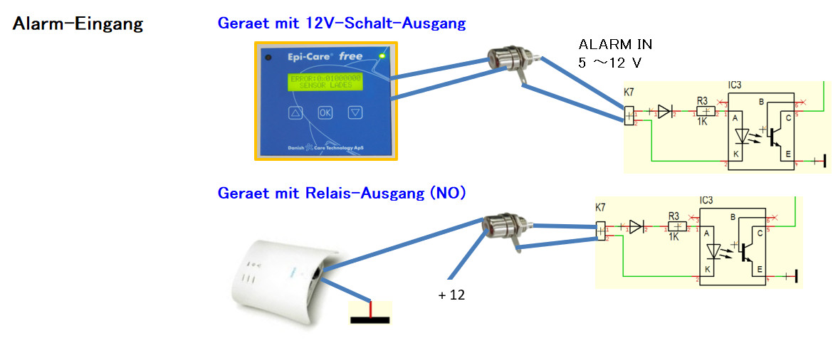 :: Alarm-Ausgang :: Alarm output Wenn kein GSM zu Verfuegung steht (GSM-Netz nicht vorhanden oder kein GSM-Shield), dann kann ein Summer angeschlossen werden, der sich im Zimmer der Betreuungsperson befindet. In case you do not use an GSM shield you could connect other alarm devices as telephon dial unit, a buzzer or anything similiar to alarm the person in charge in a room next door. 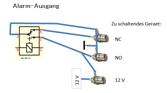 :: Diagramm der Zeitschaltuhr siehe hier. :: Diagram of the timer see here. :: ISP-Programmer (FT232 USB to Serial Communication Board)Zum Flashen des ATmega328.For flashing the ATmega328  Reset-Taster Reset-Taster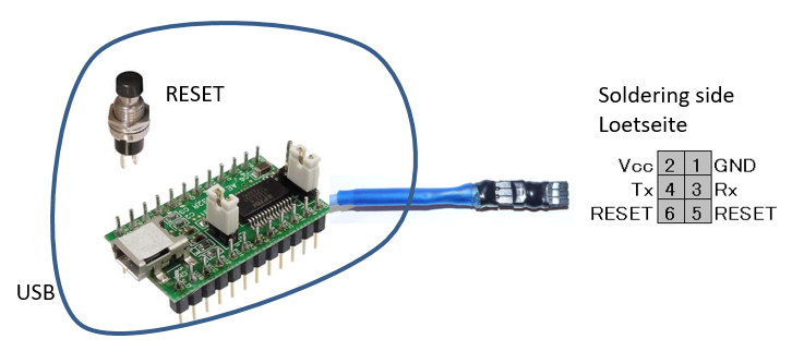 No.5 and 6 to Reset button Der Reset-Taster entspricht dem Reset-Taster auf der Epidino-Platine. The reset button corresponds to the reset button on the Epidino board. For more information see: FT232RL USB to Serial Breakout Board https://www.arduino.cc/en/Main/Standalone Hier wird der Programmer angeschlossen (hellgruen gekennzeichnet) Here the programmer is connected (light green marked) 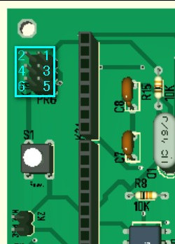 Man drueckt die Reset-Taste, klickt "Hochladen" (Pfeil nach rechts) und laesst die Reset-Taste los, sobald unten in der Info-Leiste "Hochladen" angezeigt wird. Press the Reset button and click "Upload" (right arrow). Release the Reset button when "Upload" is shown in the info line. 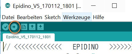 Open-source Arduino
Software (IDE) Open-source Arduino
Software (IDE) Einstellung im Menue "Werkzeuge": Arduino Uno, Port xx, AVRISP mkII Setting in menu "Tools": Arduino Uno, Port xx, AVRISP mkII Man kann natuerlich auch einfach den ATmega328 in einem Arduino Uno flashen und dann in die Epidino-Platine stecken. Of course, you can also simply flash the ATmega328 in an Arduino Uno and then insert it into the socket of the Epidino board. :: Und hier der Code. Updated: 2018-01-20 :: The code Da der Code staendig geaendert wird, bitte nach der neuesten Version fragen unter mail(ät)dk2os(Punkt)net As the code changes frequently please ask for the newest version. mail(ät)dk2os(Punkt)net >>> Download Epidino Code (.txt) >>> Download Epidino Code (.pdf) Es oeffnet sich ein neuer Tab. Bitte alles kopieren und in Arduino IDE ablegen. Please copy the code which will be shown in a new tab and paste into Arduino IDE. Um die mit den drei Potentiometern eingestellten Werte auf dem Monitor zu sehen, den ISP-Programmer anschliessen und im Menue "Werkzeuge" der Arduino Software (IDE) "Serieller Monitor" waehlen. To monitor the values set by the three pots please connect the ISP programmer and select "Serial Monitor" in Menue "Tools" in the Arduino Software (IDE). 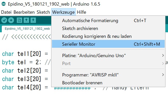 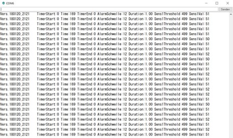 >>> Erklaerung zur Einstellung der Potentiometer (pdf) >>> Explanation of the potentiometer for adjustment (pdf) |
Besucherz�hler Html
